plasma cutter cutting guides

Plasma Cutter Cutting Guides: An In-Depth Overview (February 18, 2026)
Today’s date is February 18, 2026․ This comprehensive guide details plasma cutter operation, settings, and troubleshooting, covering amperage, air pressure, and feed rates for optimal results․
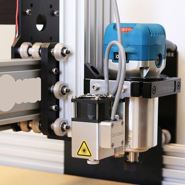
Plasma cutting is a versatile process utilizing a high-velocity jet of ionized gas to melt and remove material․ This technique excels at cutting electrically conductive materials like steel, aluminum, and stainless steel․ Modern plasma cutters, when paired with CNC machines like those from Stepcraft, can effectively cut up to 5/8 inch mild steel․
Understanding proper setup – including air pressure (60-70 psi), amperage, pierce height, and feed rate – is crucial․ Software like FlashCut CNC aids in defining cut areas and material thickness for precise results․ Mastering these elements unlocks the full potential of plasma cutting․
Understanding Plasma Cutter Components
A plasma cutter’s core components include the power supply, air compressor/filter, plasma torch, and consumables․ The power supply generates the electrical arc, while the air compressor provides clean, dry air – typically adjusted via a regulator (60-70 psi)․
The torch directs the plasma arc, and consumables – nozzles and electrodes – focus and shape it․ Secure connections are vital, as emphasized by Koike Aronson․ Proper consumable selection, based on material type, directly impacts cut quality and lifespan․

Safety Precautions for Plasma Cutting
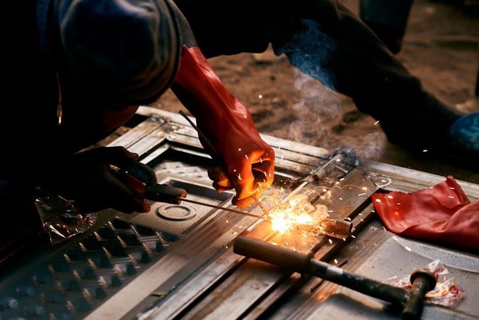
Plasma cutting demands strict safety adherence․ Always wear appropriate personal protective equipment (PPE), including welding helmets, gloves, and fire-resistant clothing․ Ensure adequate ventilation to avoid fume inhalation; A solid ground connection is crucial, preventing electrical shock․
Be mindful of the intense heat and sparks generated; clear the work area of flammable materials․ Never cut near pressurized containers․ Regularly inspect equipment for damage, and disconnect power when not in use․
Material Compatibility and Thickness Limits
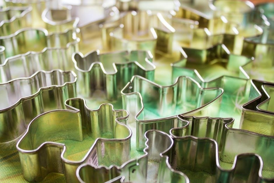
Plasma cutters excel with electrically conductive metals․ Mild steel, aluminum, stainless steel, and copper are commonly cut․ However, non-metals and certain alloys pose challenges․ Cutting capacity depends on the machine’s amperage; a CUT 50 can handle up to 5/8” mild steel․
Thicker materials require higher amperage and slower feed rates․ Exceeding thickness limits results in incomplete cuts or damage to the equipment․ Always consult the manufacturer’s specifications․
Air Pressure Settings for Optimal Cuts
Proper air pressure is crucial for clean, efficient plasma cuts․ Typically, manufacturers recommend 60-70 PSI, adjusted via the regulator knob on the back of the unit․ Insufficient pressure causes arc instability, while excessive pressure can widen the cut․
Consistent air supply ensures optimal performance․ Regularly check the filter and connections for leaks․ Fine-tuning air pressure, alongside amperage, significantly impacts cut quality and speed․
Adjusting Air Pressure Regulator
The air pressure regulator, usually a black knob, controls airflow to the plasma cutter․ Turning it clockwise increases pressure, while counterclockwise decreases it․ Monitor the pressure gauge while adjusting to achieve the desired PSI․
Ensure the regulator is clean and free of debris for accurate readings․ Gradual adjustments are key; small changes can significantly affect cut quality․ Always verify settings before initiating a cut․
Recommended PSI Ranges
Generally, a plasma cutter operates optimally within a 60-70 PSI range for most materials․ However, specific requirements vary based on material type and thickness․ Thicker materials often necessitate higher pressures for optimal penetration and clean cuts․
Always consult the manufacturer’s specifications for your specific plasma cutter model․ Experimenting within this range, while monitoring cut quality, helps fine-tune settings for best performance․
Amperage Selection Based on Material
Correct amperage is crucial for clean, efficient plasma cuts․ Adjusting amperage based on material thickness ensures proper penetration without excessive heat or slag․ Thicker materials demand higher amperage, while thinner materials require lower settings to prevent burn-through․
Always begin with manufacturer recommendations and perform test cuts, incrementally adjusting amperage until the desired result is achieved․ Proper amperage selection maximizes cut quality and consumable lifespan․
Mild Steel Amperage Guide
For mild steel up to 5/8 inch thickness, amperage settings typically range from 30 to 60 amps․ A 1/8-inch plate generally requires 30-40 amps, while 1/4-inch steel benefits from 40-50 amps․ Reaching 5/8 inch necessitates 50-60 amps for complete penetration․
These are starting points; adjust based on your specific machine and desired cut quality․ Always prioritize test cuts to fine-tune amperage for optimal performance․
Aluminum Amperage Guide
Aluminum requires different amperage settings compared to mild steel due to its thermal conductivity․ For thinner aluminum (1/8 inch), 30-40 amps are suitable․ Increasing to 1/4 inch necessitates 40-50 amps, and 3/8 inch typically requires 50-60 amps․
Precise amperage selection is crucial for clean aluminum cuts․ Always perform test cuts and adjust accordingly, considering the alloy and thickness for optimal results․
Pierce Height and Cut Height Optimization

Optimizing pierce and cut height is vital for quality; Pierce height initiates the arc, while cut height maintains it․ Incorrect settings lead to dross, angled cuts, or arc instability․ Generally, a pierce height of 0․125-0․25 inches is a good starting point․
Cut height should be slightly lower, around 0․0625-0․125 inches, depending on material and amperage․ Experimentation is key to achieving clean, precise cuts․
Impact of Pierce Height on Cut Quality
Pierce height significantly affects cut initiation and quality․ Too high, and the arc may struggle to establish, causing inconsistent starts and potential arc blow․ Too low, and it risks damaging the nozzle or creating excessive spatter․
An optimal pierce height ensures a clean, focused arc, minimizing dross formation and promoting a smooth, accurate cut․ Consistent pierce height is crucial for repeatable results․
Determining Optimal Cut Height
Optimal cut height balances arc focus and cut quality․ Generally, a smaller gap yields a narrower kerf and cleaner cuts, but increases the risk of double arcing․ A larger gap provides more clearance but can widen the kerf and reduce precision․
Manufacturers’ specifications are a starting point; experimentation is key․ Adjust based on material type, thickness, and desired finish․ Observe the cut face for signs of dross or arc instability․
Feed Rate (Cutting Speed) Charts
Feed rate, or cutting speed, directly impacts cut quality․ Too slow causes excessive heat and dross; too fast results in incomplete cuts․ Charts correlate material thickness with optimal speeds, providing a starting point for adjustments․
CNC plasma cutting demands precise feed rate programming․ Consider lead-in/lead-out speeds and corner deceleration․ Stepcraft, Inc․ highlights settings for up to 5/8” mild steel, emphasizing the need for tailored adjustments․
Relationship Between Material Thickness and Feed Rate
A direct, inverse relationship exists between material thickness and feed rate․ Thicker materials necessitate slower speeds to ensure complete penetration․ Conversely, thinner materials require faster speeds to minimize heat input and distortion․
As thickness increases, the plasma arc requires more time to sever the material․ Charts provide baseline speeds, but experimentation is crucial․ Adjustments depend on amperage, air pressure, and the specific material composition․
CNC Plasma Cutting Feed Rate Considerations
CNC plasma cutting demands precise feed rate control for clean, accurate cuts․ Software like FlashCut CNC allows defining material thickness, influencing calculated speeds․ Lead-in and lead-out tabs compensate for arc start/end delays, preventing incomplete cuts․
Cornering requires speed reduction to maintain arc stability․ Proper nesting optimizes material usage, while consistent feed rates minimize errors․ Regularly calibrate your CNC machine for optimal performance․
Consumable Selection and Maintenance
Choosing the right nozzles and electrodes is crucial for plasma cutter performance․ Different materials require specific consumables for optimal cutting․ Regularly inspect for wear – pitting, erosion, or damage – and replace as needed․
Maintaining clean consumables extends lifespan․ Avoid contamination and ensure proper air pressure․ Following manufacturer guidelines for replacement intervals maximizes efficiency and cut quality, reducing downtime․
Choosing the Right Nozzles and Electrodes
Selecting appropriate consumables directly impacts cut quality and efficiency․ Confirm the correct nozzle and electrode are used for the material being cut – mild steel, aluminum, or stainless steel each demand specific types․
Consider material thickness; thinner materials often require smaller orifice nozzles․ Always verify compatibility with your plasma cutter model․ Using incorrect consumables leads to poor cuts and premature wear․
Extending Consumable Lifespan
Proper maintenance significantly extends the life of nozzles and electrodes․ Ensure consistent air pressure (60-70 psi) and avoid contamination in the air supply․ Regularly inspect consumables for wear, replacing them proactively before performance degrades․
Maintain a solid ground connection to minimize electrode erosion․ Correct amperage settings, tailored to material thickness, also reduce wear․ Store consumables properly to prevent damage․
Ground Clamp Placement and Importance
A secure ground connection is critical for stable arc initiation and cut quality․ Attach the ground clamp directly to the workpiece, as close to the cutting area as possible․ If that’s not feasible, clamp to the workbench, ensuring a clean, metal-to-metal contact․
Poor grounding causes arc instability and poor cuts․ Regularly check connections for corrosion or looseness, and address any issues immediately to maintain optimal performance․
Ensuring a Solid Ground Connection
Achieving a robust ground is paramount for successful plasma cutting․ Remove any paint, rust, or coatings from the clamping area to expose bare metal․ Utilize a heavy-duty ground clamp and cable, ensuring a tight, secure grip․
Periodically inspect the connection during operation․ A weak ground manifests as erratic arcs or difficulty initiating a cut; re-establish a firm connection immediately for consistent results․
Troubleshooting Grounding Issues
Arc instability often signals grounding problems․ First, verify the ground clamp’s physical connection – it must be clean, bare metal contact․ Check the ground cable for damage or breaks; replace if necessary․
Try repositioning the clamp closer to the cutting point․ If issues persist, inspect the machine’s internal grounding․ Poor grounding leads to inconsistent cuts and potential machine damage, so address it promptly․
Straight Line Cutting Guides and Techniques
Achieving straight cuts manually requires assistance․ Utilizing angle iron guides provides a stable reference edge for the torch․ Securely clamp the guide to the workpiece, ensuring it’s perfectly aligned with the desired cut line․
However, manual guides have limitations, especially on complex shapes or long cuts․ For precision, consider CNC plasma cutting, which offers automated straight-line capabilities and superior accuracy․
Using Angle Iron Guides
Angle iron guides are a cost-effective solution for manual straight cuts․ Two-inch by two-inch extruded aluminum angle, approximately 1/8th inch thick, works well․ Clamp these guides firmly to the workpiece, ensuring they are precisely aligned with your intended cutting path․
The guide provides a consistent edge for the plasma torch to follow, improving cut accuracy․ Remember to account for the torch’s offset from the edge when positioning the guide․

Limitations of Manual Guides
Manual guides, while helpful, present inherent limitations․ Maintaining consistent torch alignment and speed is challenging, leading to potential inconsistencies in cut quality, especially over longer distances․ Achieving precise 90 and 45-degree angles reliably proves difficult without specialized tooling․
The value of more sophisticated methods becomes apparent when comparing results․ Manual guides are best suited for simpler cuts and offer a stepping stone before investing in CNC automation․
Plasma Cutter Settings Charts for Common Materials
Optimal settings are crucial for clean cuts․ Charts provide starting points for amperage, air pressure, pierce height, cut height, and feed rate, varying by material and thickness․ For mild steel up to 5/8 inch, and aluminum of various thicknesses, these charts offer guidance․
Remember, these are starting points; adjustments may be needed based on your specific plasma cutter and material conditions․
Chart for Mild Steel (Up to 5/8 inch)
This chart details settings for mild steel up to 5/8 inch thick․ Air pressure should be initially set around 60-70 PSI, adjusted via the regulator․ Amperage varies with thickness; thinner steel requires lower amperage․ Pierce height and cut height are critical for quality․
Feed rates (cutting speed) depend on both amperage and material thickness – consult a comprehensive feed rate chart for precise values․
Chart for Aluminum (Various Thicknesses)
Aluminum cutting demands precise settings․ Begin with air pressure around 60-70 PSI, fine-tuning for optimal results․ Amperage must be adjusted based on aluminum thickness; thicker material needs higher amperage․ Correct consumable selection is vital for aluminum․
Pierce and cut heights significantly impact cut quality․ Refer to a detailed feed rate chart correlating material thickness, amperage, and cutting speed for best performance․
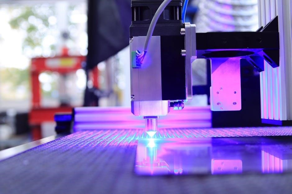
Software Integration for CNC Plasma Cutting
CNC plasma cutting relies heavily on software․ Programs like FlashCut CNC enable design loading and programming, defining cut areas and material thickness accurately․ Software streamlines the process, translating designs into machine instructions․
Proper software integration ensures precise control over parameters like feed rate and amperage․ This minimizes errors and maximizes cutting efficiency, leading to cleaner, more accurate results․ Careful setup is crucial․
Using FlashCut CNC for Design and Programming
FlashCut CNC is a powerful tool for plasma cutting․ It allows users to load designs and define critical parameters, including material thickness and cut areas․ This software translates designs into G-code, the language understood by CNC machines․
Users can optimize cutting paths and adjust settings directly within FlashCut, ensuring precision and efficiency․ Mastering this software is key to unlocking the full potential of your CNC plasma setup․
Defining Cut Areas and Material Thickness in Software
Accurate software setup is crucial for successful plasma cuts․ Within programs like FlashCut CNC, precisely define the areas to be cut from your design․ Inputting the correct material thickness is equally vital, as this directly impacts amperage, feed rate, and overall cut quality․
Incorrect thickness settings can lead to incomplete cuts or excessive dross․ Double-check these parameters before initiating any cutting operation․
Troubleshooting Common Plasma Cutting Problems
Addressing issues promptly ensures efficient operation․ Poor cut quality often stems from incorrect settings – review amperage, air pressure, and feed rate․ Arc instability can indicate a faulty ground connection or worn consumables․ Regularly inspect nozzles and electrodes for damage․
Consistent troubleshooting and preventative maintenance will minimize downtime and maximize the lifespan of your plasma cutter․
Addressing Poor Cut Quality
Substandard cuts demand immediate attention․ Begin by verifying amperage settings are appropriate for the material thickness․ Incorrect air pressure (typically 60-70 psi) can cause dross or incomplete cuts․ Ensure proper pierce and cut heights are maintained for clean separation․
Inspect consumables; worn parts significantly degrade cut quality․ Adjust feed rate – too fast causes incomplete cuts, too slow leads to excessive heat․
Resolving Arc Instability
An unstable arc hinders precision and safety․ First, confirm a solid ground connection; poor grounding is a frequent culprit․ Check for loose connections in the torch and air lines, impacting gas flow․ Verify correct consumable installation and condition, as worn electrodes cause instability․
Fluctuating air pressure can also contribute; regulate it consistently․ Finally, examine the material for contaminants affecting arc initiation․